Project Setup
In this window you define the geometry for the excavation surface that you will analyse, and the volume of the DFN.
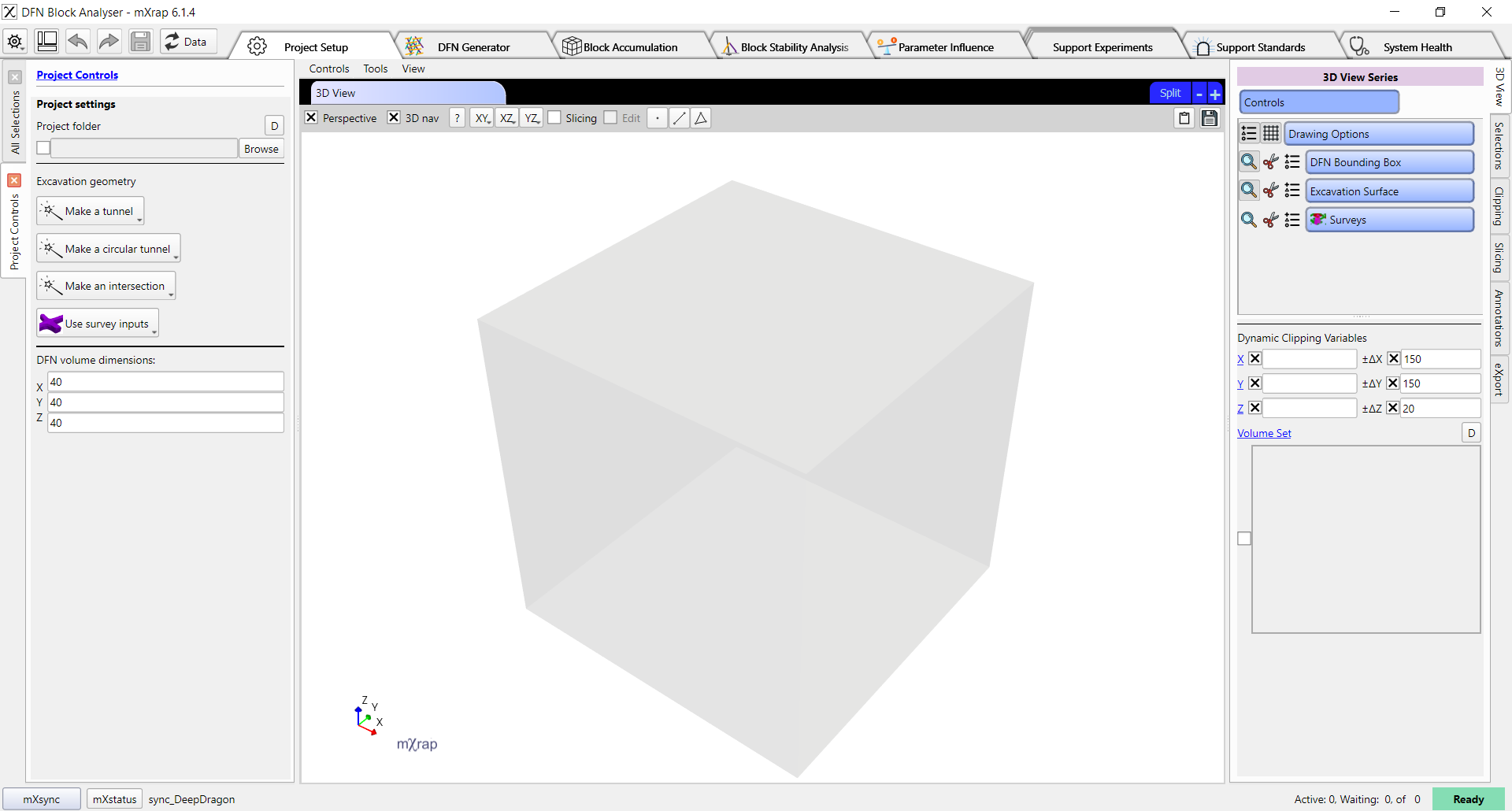
In the control panel on the left, the Project folder input specifies a folder to store the accumulated blocks for this project. You can open the project again at a later date to continue stability analysis using the accumulated blocks. Note that you can only accumulate new blocks if your excavation geometry matches the previous excavation geometry, we recommend saving a workspace of your project to save the excavation geometry settings, project folder, and selected DFN parameters file.
The excavation geometry can be based on survey files (e.g. your own designs or asbuilts), or it can be created according to preset shapes: tunnels, circular tunnels, or intersections. In the current version, only the preset tunnel option can be used with ground support standards.
Predefined excavation geometries
If you click on the tunnel, circular tunnel, or intersection options then the control panel will update to show input parameters for the geometry.
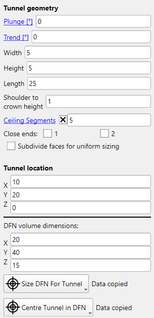
- Plunge defines the plunge of the tunnel (or one axis of the intersection). Plunge is always in the direction of trend.
- Trend defines the trend of the tunnel.
- Width defines the width of the tunnel.
- Height defines the height of the tunnel, from the floor to the crown.
- Length defines the length of the tunnel.
- Shoulder to crown height is used for creating arched backs. It specifies the height of the arch.
- Ceiling segments specifies the number of segments used when creating arched backs. More segments will create a smoother arch, but will increase the processing time of block accumulation.
- Close ends controls whether the end of the tunnel is closed or open. If a tunnel has a closed end that is within the DFN volume, then blocks may accumulate on the end. This may be useful if you wish to analyse block formation on the face, but there are limited tools for this analysis at this time.
- Subdivide faces for uniform sizing we recommend turning this option off for the block analyser. The subdivision of faces will increase the processing time of block accumulation, and provides no benefit for this application.
- Tunnel location specifies the coordinates of the centre of the floor of the tunnel.
- DFN volume dimensions specifies the volume that joints will be generated in.
The Size DFN For Tunnel button can be used to quickly resize DFN volume and place the tunnel in the middle of the volume. It usually provides a reasonable default, but you may wish to customise the location or volume according to your use case.
Joints are only generated within the DFN volume, so the DFN volume must extend far enough around your excavation surface to capture the largest blocks that you could anticipate. Note that the edge effect of joint generation is already mitigated by the DFN generator, so you do not need to oversize your DFN volume to account for edge effects. The larger the DFN volume is, the more time that DFN generation will take and the more time that block finding will take.
Excavation geometry from survey inputs
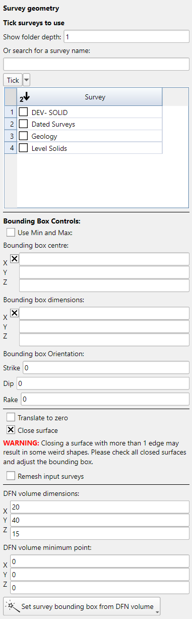
If you click on Use survey inputs then the control panel will update to show you settings for selecting a survey, clipping and optionally remeshing the survey, and positioning the DFN volume.
The following is a good process to follow for using survey inputs. First, in the 3D View Series controls, turn off the DFN Bounding Box and Excavation Surface, then turn on the Surveys series. In the Surveys series options, turn on the survey that you want to use. Then click on the 3D View and press the R button to reset the view.
You should now be able to see your surveys. You can zoom in to an area of interest by hovering the mouse over a point on the surveys and pressing the F key. Once you have found an area of interest, we want to position the DFN volume there. There are two convenient ways to find the coordinates:
- Using the annotations tool, place a point on the survey and then read the coordinates of that point.
- Turn off Perspective in the 3D view, then use the XY, XZ, YZ buttons to align the view so that you can read the coordinates from the grid.
Now, turn on the DFN Bounding Box series and then type your coordinate in the DFN volume minimum point input at the bottom of the panel. You should see a transparent grey box indicating the DFN volume in the 3D view. Adjust the minimum point and the volume dimensions to cover your area of interest.
When you have the position correct, turn off the Surveys series and turn on the Excavation Surface series. Now tick the survey in the table in the control panel on the left. To begin with you should see all of the survey, but we want to clip the survey to the area of interest so that the block finding process will be more efficient. At the bottom of the control panel click on the Set survey bounding box from DFN volume button.
By default the surface is clipped exactly to the DFN volume, and also closed by attempting to automatically fill any holes in the survey. We will adjust our bounding box minimum and maximum so that the clipping area is slightly larger than the DFN volume, and we will untick the Close surface option.
If your surveys have quality issues such as internal surfaces, holes, self-intersections, or non-manifold topology then they will cause problems with the block-finding process. There is an integrated remeshing option which can fix some of these problems. To enable it, tick the Remesh input surveys option in the control panel. If the remesher fails or there are still quality issues then you will need to correct your input surveys in external software.